
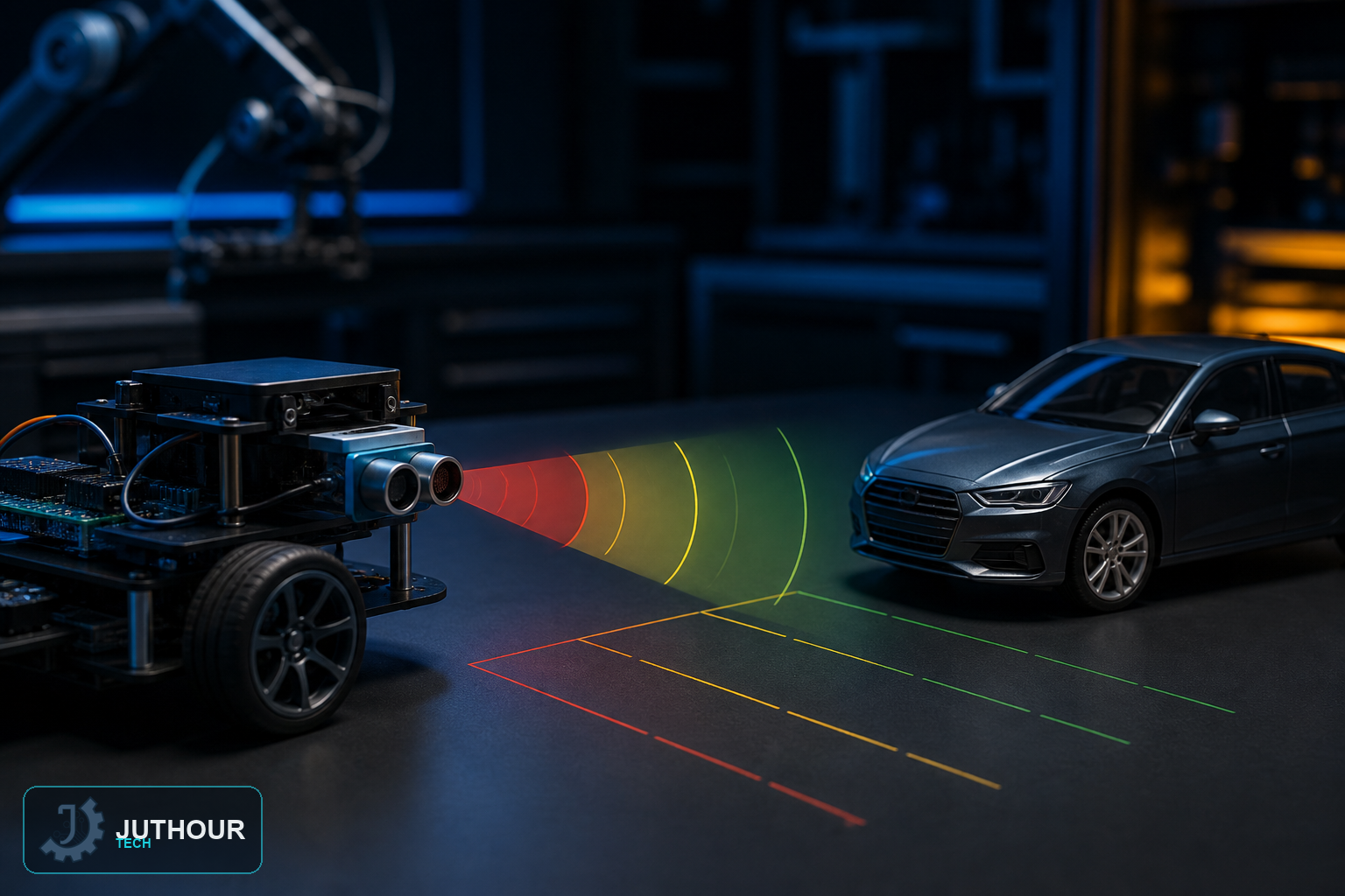
Explore ultrasonic ranging on a stationary vehicle model and document why automotive blind-spot functions require certified hardware and validation.
Prototype objective
This project focuses on measurement, state logic, feedback, and a low-voltage bench prototype that can be tested safely before any more advanced application is considered.
Suggested components
An Arduino Uno R3, an HC-SR04 ultrasonic sensor, a 16x2 I2C LCD, a 5V active buzzer, a 5mm yellow LED, a breadboard, and jumper wires.
Wiring and implementation
The HC-SR04's Trig and Echo pins connect to pins 12 and 13, the buzzer connects to pin 3, the LED to pin 4, and the LCD uses I2C wiring needing just two signal lines.
Use a regulated supply and common ground, drive loads through suitable interface stages, add flyback protection for inductive loads, and condition logic levels where required.
Test plan
Use a stationary scale model to test target angle, speed simulation, rain, vibration, and missed echoes; do not install the prototype on a road vehicle.
Use limitations
Hobby ultrasonic sensors are not automotive blind-spot sensors and may miss vehicles. Never use this prototype for lane-change decisions or install it on a road-going vehicle.
Next step
Document the schematic, library versions, measurements, and failure cases before extending the prototype, and consult qualified specialists and applicable standards whenever safety, health, vehicles, or industrial equipment are involved.
Leave your comment