
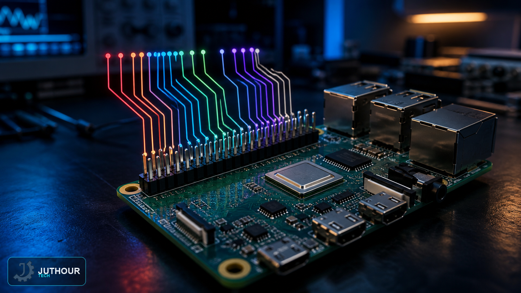
The Raspberry Pi header mixes power rails, grounds and configurable signals. Before connecting a sensor, identify both the physical pin position and the Broadcom GPIO number used by software.
From 26 pins to 40 pins
Early Raspberry Pi Model A and Model B boards used a 26-pin header. The 40-pin format was introduced with Raspberry Pi 1 Model B+ and retained by later full-size boards. The first 26 positions remain broadly compatible, while later pins add more GPIO and ground connections. Some Raspberry Pi Zero models have the 40-pin footprint without a fitted header.
Physical numbering and BCM numbering
Physical numbering describes the connector position from 1 to 40. BCM numbering refers to the SoC GPIO channel and is the convention used by many libraries. These numbers are not interchangeable; declare the numbering mode explicitly in software and verify it before wiring.
Power and voltage limits
GPIO signals use 3.3V logic and are not 5V-tolerant. The header also exposes 3.3V, 5V and ground pins, but a power pin is not a programmable GPIO. Use a proper level shifter for 5V logic, and a transistor or driver for motors, relays and other high-current loads.
Interfaces and reserved pins
Selected GPIO pins can provide I2C, SPI, UART or PWM alternate functions. Physical pins 27 and 28 (GPIO0 and GPIO1) are reserved for identification and advanced uses on many HAT designs, so avoid them unless the hardware specification requires them.
Check the board in front of you
Run pinout in Raspberry Pi OS when the GPIO Zero tools are installed, and compare the result with the official board documentation. Never wire from memory when a mistaken 5V connection can damage the board.
Leave your comment