
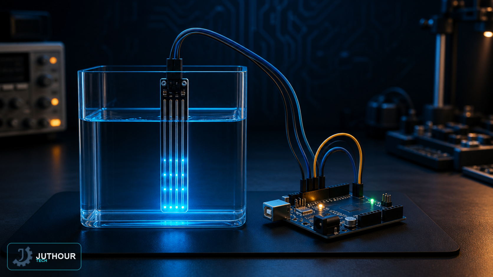
A water level sensor measures how high liquid rises inside a tank or container based on a simple electrical-conduction principle, with no moving parts or mechanical floats at all.
Components needed
An Arduino board, a water level sensor, and connecting wires.
How it works internally
The sensor board contains ten exposed copper traces arranged alternately: five power traces and five sensing traces, with each sensing trace positioned between two power traces. When dry, these traces stay completely electrically disconnected; but when water touches them, it acts as a conductor linking the power and sensing traces, so the sensing traces together act as a variable resistor much like a potentiometer, whose value changes with how deep the traces are submerged: the more water contact, the lower the resistance, and vice versa.
Wiring it up
The sensor connects with three pins: the signal pin (S) to an Arduino analog input (A0) to read the resulting voltage, the power pin (VCC) to 3.3-5V (preferably through a digital pin like pin 7 to enable intermittent operation), and ground (GND) as a common reference.
You can find water level sensors at Juthour Tech.
Leave your comment