
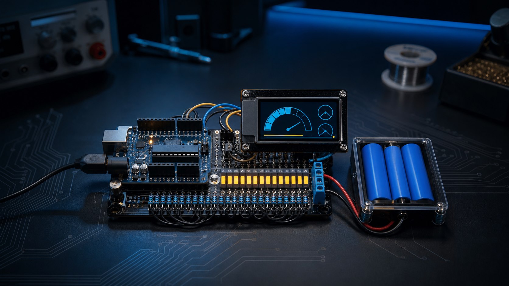
An Arduino analog input can measure battery voltage and display it on a ten-segment LED bar, but the voltage must first be reduced to a safe input range. This build measures up to about 15V through a 5:1 divider and averages multiple samples for a more stable result.
Edition note: This English edition was technically revised and published in August 2026. The original Arabic article was published on July 28, 2021.
Measurement principle
The 10-bit ADC in an Arduino Uno converts the range from ground to its reference voltage into codes from 0 to 1023. A 30kΩ resistor from battery positive to the measurement node and a 7.5kΩ resistor from that node to ground form a divider ratio of about 5:1. A 15V battery therefore produces about 3V at A0.
The general equation is Vbattery = ADC × (Vref / 1023) × ((R1 + R2) / R2). Measure the board's actual 5V rail with a multimeter and use that value as Vref when better accuracy is required.
Parts and wiring
- Arduino Uno and a ten-segment LED bar or ten individual LEDs.
- Ten 220Ω or 330Ω current-limiting resistors, one per LED.
- 30kΩ and 7.5kΩ divider resistors, preferably 1% tolerance.
- Optional 100nF capacitor from A0 to GND to reduce high-frequency noise.
| Connection | Route |
|---|---|
| Battery positive | Through R1=30kΩ to the A0 node |
| A0 node | Through R2=7.5kΩ to GND |
| Battery negative | Arduino GND |
| LED segments | D2 through D11, each through its own resistor |
Arduino sketch
const byte VOLTAGE_PIN = A0;
const byte ledPins[10] = {2, 3, 4, 5, 6, 7, 8, 9, 10, 11};

const float VREF = 5.00;       // Replace with the measured 5V rail
const float R1 = 30000.0;
const float R2 = 7500.0;
const float DIVIDER_RATIO = (R1 + R2) / R2;
const float DISPLAY_MAX_VOLTAGE = 15.0;

float readBatteryVoltage() {
  unsigned long sum = 0;
  const byte samples = 16;
  for (byte i = 0; i < samples; i++) {
    sum += analogRead(VOLTAGE_PIN);
    delay(3);
  }
  float raw = sum / float(samples);
  float pinVoltage = raw * (VREF / 1023.0);
  return pinVoltage * DIVIDER_RATIO;
}

void showLevel(float voltage) {
  int lit = int((voltage / DISPLAY_MAX_VOLTAGE) * 10.0 + 0.5);
  lit = constrain(lit, 0, 10);
  for (byte i = 0; i < 10; i++) {
    digitalWrite(ledPins[i], i < lit ? HIGH : LOW);
  }
}

void setup() {
  Serial.begin(9600);
  for (byte i = 0; i < 10; i++) pinMode(ledPins[i], OUTPUT);
}

void loop() {
  float voltage = readBatteryVoltage();
  showLevel(voltage);
  Serial.print("Battery voltage: ");
  Serial.print(voltage, 2);
  Serial.println(" V");
  delay(500);
}
Calibration and limitations
Compare the result with a trusted multimeter at several voltages, then adjust Vref or the divider ratio if the error is consistent. Recalculate resistor power for higher voltages and add a fuse and reverse-polarity protection in permanent installations.
The ten LEDs represent a fraction of the configured 0–15V measurement span; they do not provide an accurate state-of-charge percentage. Voltage-to-charge relationships vary with battery chemistry, load, temperature, and rest time. A true fuel gauge requires a method designed for the specific battery system.
Leave your comment