
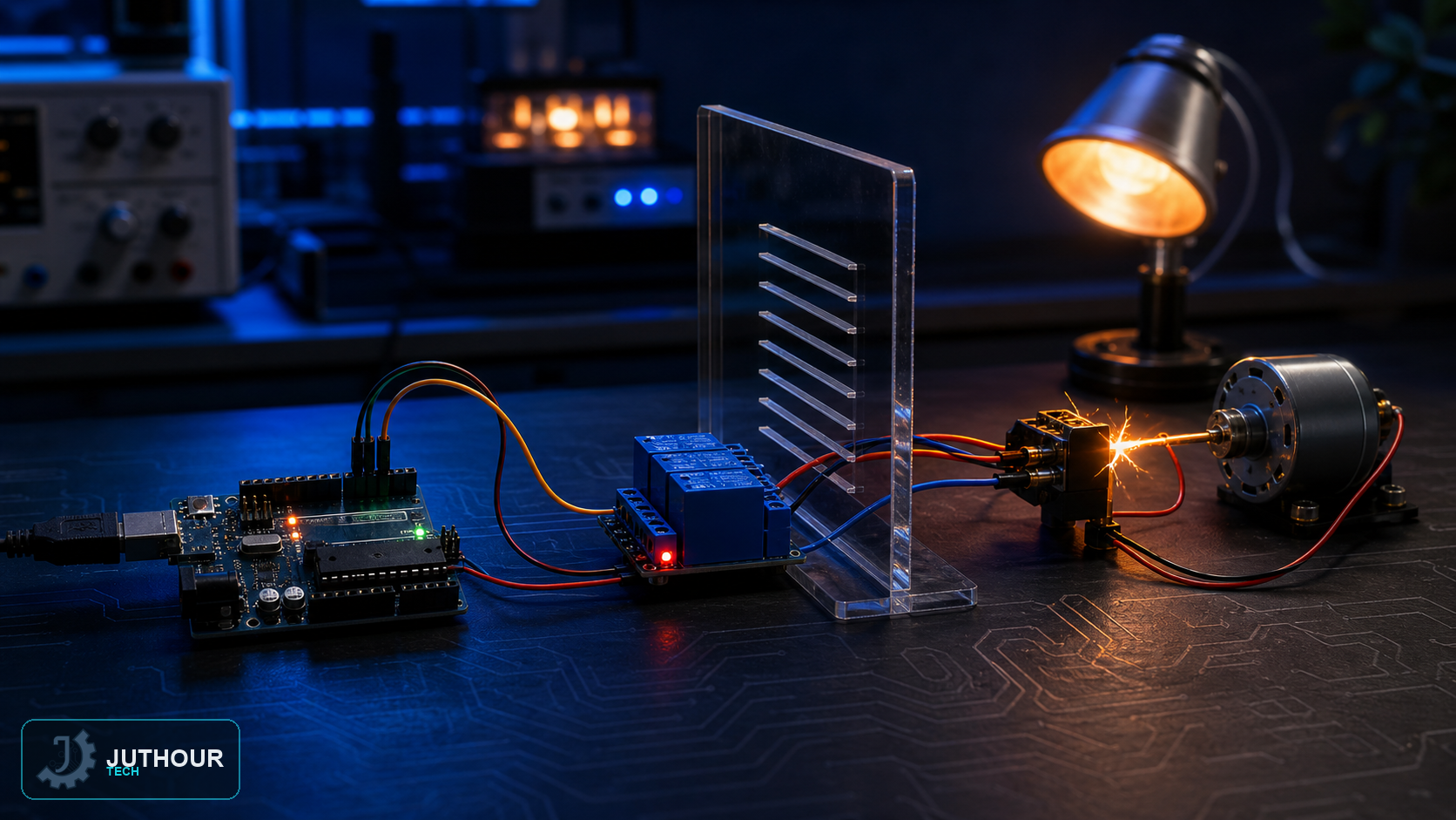
A relay lets a low-voltage signal — like Arduino's 5V output — control circuits at much higher voltages, including devices running on household mains power, which makes it one of the most useful and most dangerous components at the same time.
Components needed
An Arduino board, a relay module (usually with one, two, or more channels), and the device to be controlled.
Wiring it up
The relay connects to Arduino through four simple pins: power and ground (VCC and GND), and one or two control pins (IN1 and IN2 on two-channel modules) connected to digital Arduino pins. Most modules include a jumper linking VCC to JD-VCC, letting the relay's electromagnetic coil be powered directly from the Arduino's supply with no separate electrical isolation needed in simple projects.
How it works
The relay contains an electromagnetic coil that opens or closes a mechanical contact when energized, allowing or blocking current through the high-voltage circuit, with no direct electrical connection between the low-voltage control circuit and the controlled circuit.
You can find relay modules with various channel counts at Juthour Tech.
اترك تعليقا