
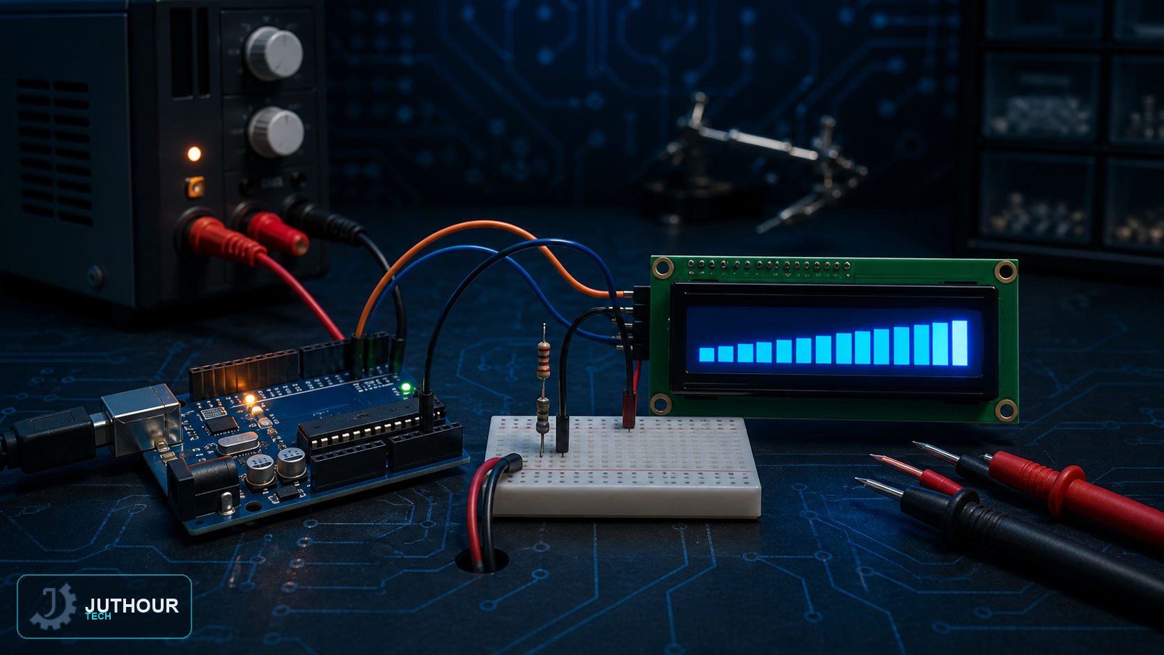
After learning the voltage-divider principle and measuring voltage with Arduino, the idea can be turned into an actual measuring tool: a standalone digital voltmeter with its own display, instead of just showing the value on the serial monitor connected to a computer.
Components needed
An Arduino Uno board, a 16x2 LCD screen, a 10k-ohm and a 100k-ohm resistor to build the voltage divider, and connecting wires.
Wiring it up
The voltage divider is built from a 10k-ohm and a 100k-ohm resistor in series, giving roughly a 1:10 division ratio, and the divided voltage connects to analog pin A0. The LCD connects using the usual digital pins (or via an I2C module to cut down on wiring, as in earlier projects).
How it works
The core idea relies on the same voltage-divider formula covered earlier:
Vout = Vin * (R2 / (R1 + R2))
The difference here is that the code applies the formula in reverse to recover the original voltage Vin from the digital reading between 0 and 1023 that the internal ADC provides. With roughly a 1:10 division ratio, voltages up to about 55V DC can be measured safely, even though the actual voltage reaching the Arduino pin never exceeds 5V. The reading updates continuously on the LCD, turning it into a practical measuring tool ready for direct use on the workbench.
You can find LCD screens and the resistors needed for this project at Juthour Tech.
اترك تعليقا